Roof collapses can be sudden, catastrophic events caused by a particular loading condition or combination of loads. Roof collapses often happen with little or no warning, making this a particularly dangerous event. When investigating a roof collapse, the obvious perpetrators are examined: how much snow was on the roof, were the drains plugged up, were the winds in excess of the design wind speed and many others. Occasionally, the roof can be doomed to collapse months or years before an event due to design or construction related deficiencies allowing for a subrogation opportunity to recover cost of repairs.
Loads on a roof can be in any direction. Rain and snow loads impose a positive pressure downward, wind loads with the right configuration can cause a negative pressure (uplift), and wind and seismic loads can create in-plane loads. These loads need to be accommodated through the structural design of the building to be safely transferred through the structure into the foundation. With the positive or negative loads, this is often accomplished through bending theory of the steel bar joists that are supporting the deck. In the case of rain or snow, the bar joist tends to bend and deflect downward. This creates tension in the bottom chord and compression in the top chord. With enough compression in the top chord the chord can buckle, just like a long slender column. To prevent this, the top chord is ‘braced’ against buckling by attaching it to the deck. Usually not too difficult, the problem however is the bottom chord.
As in the scenario described above, but with the load going up, like with wind over a low slope roof, the top chord becomes in tension and the bottom chord in compression. As the properties of the steel and geometry have not changed, the bottom chord becomes susceptible to buckling. Consequently, this is why in buildings such as large box retail stores, one can see braces spaced five to ten feet on center from the bottom chord to the top. The absence of these braces leaves the bottom chords of the roof structure susceptible to buckling and collapse during a high velocity wind event.
Impeding the roof drainage can also create a serious loading condition. Rain usually is not meant to accumulate on a roof for very long, and when it is designed to hold water, the supporting structure is designed accordingly. Where a building has a continuous parapet, the drainage of the roof is accommodated completely by the drainage system, whether it is internal drains or scuppers through the parapet. The most recent building codes typically require a secondary system if a continuous parapet is used. In the event that the primary drainage system is overwhelmed or clogged, a secondary system can safely convey water off the roof. The secondary system can be internal drains plumbed separately from the primary system or scuppers through the parapet. Why is this required? Take a typical bar-joist supported steel deck with a built-up membrane and a few inches of insulation for example. This configuration may be on a school, warehouse, retail, or any number of structures. It would only take about three inches of water to equal the dead weight (weight of the deck, joists, etc.) of the roof. In other words, if a plastic bag blew onto the roof that plugged the roof drain, the omission of a secondary drainage system or an under-designed drainage system has just precariously doubled the load on the roof. Many older buildings do not have secondary drainage systems. The “grandfather clause” is often cited to indicate that existing building conditions are not required to comply with current code requirements. However, if an existing building roof is replaced, the roof drainage system should be revised to ensure it complies with the current codes, which would include a secondary drainage system. In most cases, the secondary drainage system is not done by the roofer.
Often, excessive ponding on a roof that leads to its collapse is the result of improper pitch of the roof toward the provided drains. Locations of ponding are easy to identify on a roof and should be corrected as soon as possible to eliminate the problem and prevent progressive aggravation of the issue, which frequently leads to the ultimate collapse of the roof. Ponding will quickly discolor the roofing. Water that sits on the roof in one area too long intensifies the effects of UV radiation on the roof causing it to fade and discolor.
Proper slope of a low-slope roof to interior roof drains is very difficult to create and requires consideration during the design of the roof framing, installation of the roof insulation, and location of roof top units. Proper slope of the roof should start with pitch of the framing to the intended low points and location of the roof drains. This requires coordination between the design architect and engineer. Next, tapered insulation can be used to create positive slope toward the location of the roof drains; however, tapered insulation is a costly, initial out of pocket expense that is often cut because it is considered unnecessary. Finally, the location of any roof top units, or skylights, must be considered and coordinated during the design phase. Frequently, excessive ponding is found on the upper side of a unit that is preventing water from continuing toward a roof drain located on the other side of the unit. This condition can be fixed by installing a cricket (tapered insulation or rigid material) upstream that forces water around the obstruction; however, this is often omitted.
The above measures must be addressed during the construction of a building to ensure proper drainage of the roof, which can prevent premature failure of the roofing or collapse of the roof due to unexpected loading from ponding. When a roof is being replaced, areas of ponding should be identified before the existing roofing is removed or covered to allow a design professional to make proper modifications to prevent future ponding.
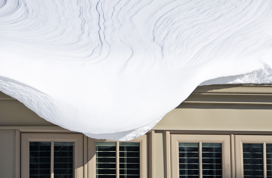
The amount of snowfall from a particular storm or harsh winter (as was experienced in parts of the Northeast during the 2013-2014 winter season) rarely exceeds the flat roof snow loads that roof systems are expected and designed to support. However, conditions such as unbalanced snow loads, drifting, sliding snow and rain-on-snow loads can drastically increase the vertical roof load on a concentrated area of the building. If the framing has not been designed to account for these conditions, it can result in catastrophic damage. Conditions such as tall adjacent building walls, high parapet signage at commercial style stores and plazas, lower roof areas abutting taller buildings, and gable shaped roofs could cause concentrated snow loading that exceed the design criteria and result in collapse. For example, a commercial plaza receives a “face-lift” and new lightweight framed parapets are installed across the front canopy to provide new prominent signage for the tenants. This new signage can cause large snow drifts to form on the roof from windward drifts across the wide open low-slope roof. If the existing roof framing is not analyzed and augmented to account for these drifts, the roof framing could collapse.
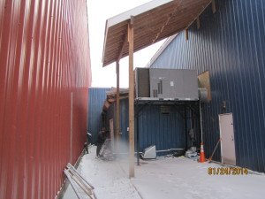
The following case illustrates how the lack of appropriate design for the site snow loading conditions caused a newly constructed storage shed addition roof in upstate New York to collapse. The storage shed was constructed against a tall industrial building and within 20’ of a second tall industrial building. The abutting building had a gable roof finished with metal roofing. Its roof sloped down toward the storage shed. The near-by building had a low-slope roof with no parapet walls or roof curbs. The shed roof collapsed after an extended cold spell. When the collapse was discovered, a large amount of snow was found on top of the shed roof. Weather records confirmed the total snowfall only equated to 0.77 inches of precipitation, or four pounds per square foot (psf). This snowfall is well below the flat roof snow load design of 30 psf that roofs in the area should be designed to support, and well below average snowfall for the region. Upon investigation, the large amount of snow on the shed roof when it collapsed resulted from snow sliding from the attached building roof and wind-blown snow from the adjacent building roof, Using design data from ASCE 7, it was found that the actual total roof load on the shed during the subject below-average snowfall was almost 50 psf, which is well over the 30 psf flat roof snow load that the roof was likely designed to support. Proper design of the roof for drifting and sliding snow would have required the roof framing be able to support a possible snow load of roughly 95 psf, more than three times what the roof was likely designed to withstand.
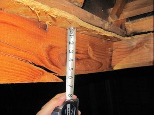
Building codes for residential structures are often more prescriptive in nature; they tend to dictate how things are built (wood studs at 16 inches on center, maximum floor joist spans, etc.) versus the performance based codes typically found with commercial construction codes. One example is the specific manner in which the International Residential Code requires that masonry be supported by wood framing. The code requires that masonry be supported by a steel lintel and three two-by-six wood members (minimum).
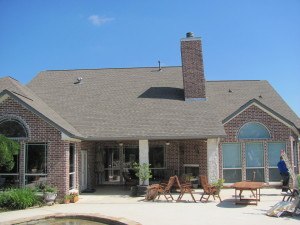
In a recent case involving a brick masonry chimney on the roof of a single family residence, the roof began to tilt, causing the roof deck to deflect about a year after construction. The supporting two-by-six rafter had failed.
The immediate concern was that the chimney would either punch through the roof deck or fall over and slide onto the patio. The investigation revealed that the code required support by three framing members and the steel lintel had not been installed. The masonry was removed from the chimney, the chimney was jacked vertical, and the framing underneath was reinforced as indicated by the IRC.
In this instance, proper code compliant framing did fall on the original contractor but that is not always the case. When building a custom home, there are many options regarding the exterior finishes, including a garage with a stone veneer gable or a hipped roof slope, siding, and a dormer. These decisions change the size of the lintel over the garage door but these selections are typically not communicated to the structural engineer whose involvement in the project has long since ended by the time the homeowner is deciding exterior finishes.
In summary, event-related loading conditions can cause catastrophic consequences on the performance of a roof structure but the design and construction of the structure can also produce imbedded defects, omissions and deficiencies that skilled forensic investigators should be able to decode to determine the cause(s) of failure and its contributing factors. Newer structures or structures with recent additions, re-roofs, or modifications where the roof has failed should be scrutinized to ensure that it was designed, built and maintained in a manner that would insure its ability to safely accommodate storm related loads.
Sarah Byer, PE is a structural engineer with 16 years of experience in commercial building design and forensic engineering investigations in the Northeast U.S. involving roof damage and failures, building envelope failures and structural assessments for code compliance. Byer is a licensed professional engineer servicing New York and New Jersey and can be reached at sarah_byer@efiglobal.com
David P. Amori, PE, RRC is a structural / geotechnical engineer and registered roof consultant with 24 years of experience in construction and engineering. He has performed hundreds of forensic investigations in North and South America including structural assessment, construction defect investigation, foundation evaluation, structural fire damage assessment and roof and building envelope assessments. Amori is vice president of engineering and can be reached at david_amori@efiglobal.com.
Was this article valuable?
Here are more articles you may enjoy.
 Charges Dropped Against ‘Poster Boy’ Contractor Accused of Insurance Fraud
  These Five Technologies Increase The Risk of Cyber Claims
  Credit Suisse Nazi Probe Reveals Fresh SS Ties, Senator Says
  Tesla Sued Over Crash That Trapped, Killed Massachusetts Driver
Want to stay up to date?
Get the latest insurance news
sent straight to your inbox.